usage of bit_vector
1. we used bit_vector to easily represent input of 4 bits, this instead of using 4 times bit pay attention this is equivalent to "DIN0,DIN1,DIN2,DIN3 : in bit".
2. access to every bit of the vector is possible by using index like DIN(0), also pay attention that based on previus statment "DIN0 = DIN(0)"
3. when we declare the bit_vector we need to give it index aka it need to be "constrained" it possible to keep it without (use just "bit_vector") index in some cases but this may cause issues with syhthesis (syhthesis will be discussed later). when we want MSB to be in left we use downto in the declaration of of the range (we will keep using downto ) for bit_vectors.
4. it possible to use to like "0 to 3" as index declaration to set the MSB to be from left, we will use such index when we will discuss strings in VHDL , for usage of string we use MSB from right and start reading string from left (simmilar to C).
5. in this example we have 4-bit mux that have 2 bits select input, as number of inputs is 4 to select them we need 2 inputs as 4 = 2^(numCtrlOfInputs) we used select as bit_vector as well size to do we use bit_vector(1 downto 0), also note if toy need a bit_vector with width of 1 bit (equaibalent to "bit") you need to use bit_vector(0 downto 0).
6. there is multiple other ways how to use vectors (slice, split, assign, others, "|" and more) we will show later with relevant examples
usage of signals
1. signals are declared on "declarative" part of the architecture aka before the begin keyword in the architecture also signal are visiable in the whole architecture.
2. signal are act as internal signal inside that logic, it can be used to connect between system parts, it also dont have meaning of in,out so we can write it in both parts of the architeture.
3. signals are static - they keep thier original value untill the user didnt add a new one.
Alternaitve (much better) way of this example here (structual design).

Below are MUX 4->1 we used to "split" it to 3 MUX 2->1 that are easily solvable using Logic gates and we used internal signals to start the intermidiate data.
Below theretical schematics

as stated before the order in the architecture is not important so the third statment the DOUT <= ... can be writted as first statment.
1. open modelsim and ensure you are in the directory where your VHD file is
2. Ensure you have work folder ready
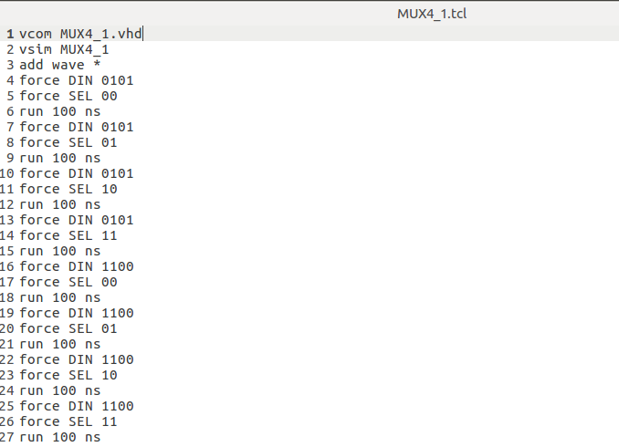
3. we use TCL based script to run the compilation and simulation process automatically
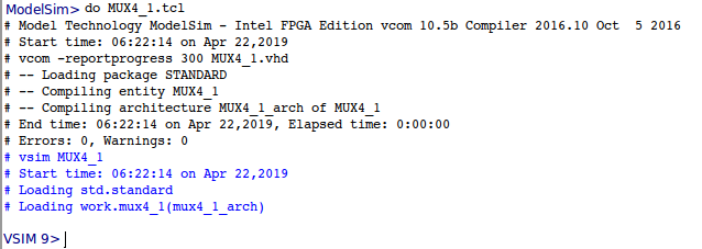
1. compilation - vcom command
2. loading entity to simulator - vsim command (no .vhd !)
3. view all waveforms of ports and internal signals - add wave *
4. stimulate and run with MISC setups, we used 2 general inputs and "scan" with SEL all the possible options.
5. note that to cover all the possible cases we will need more complex do script as system have 6 inputs so it have 64 possible cases.
we can see from waveform that below are behaive of real MUX with 4 inputs. we used to major cases in the simulation - review the TCL script.
