sometime we will want to duplicate existing H\W, for example we have 2 input AND gate and we would like to make it have much more inputs lets say 100 or even 2000, the VHDL provide several ways to achive it easilt, obviesly we will not use and operation on all the elects like y <= input(0) and input(1).... and input(100); but there is betters ways to achive it
1. we can use generate statment in architecture.
2. we can use loop statment in process.
3, we can use loop statments in function (click here for functions introduction)
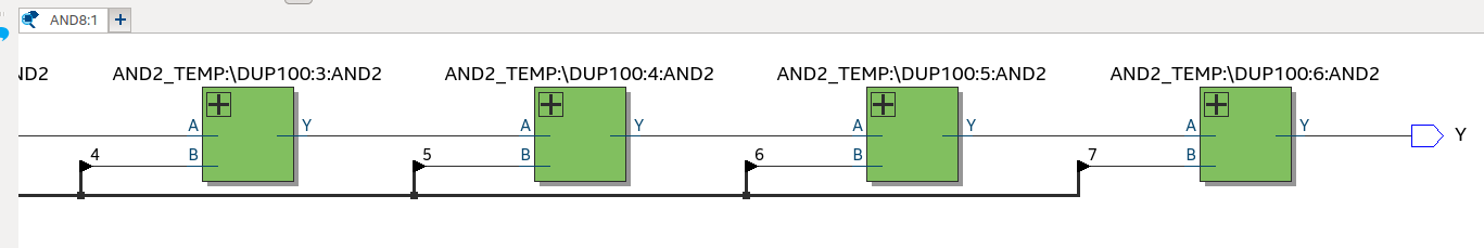
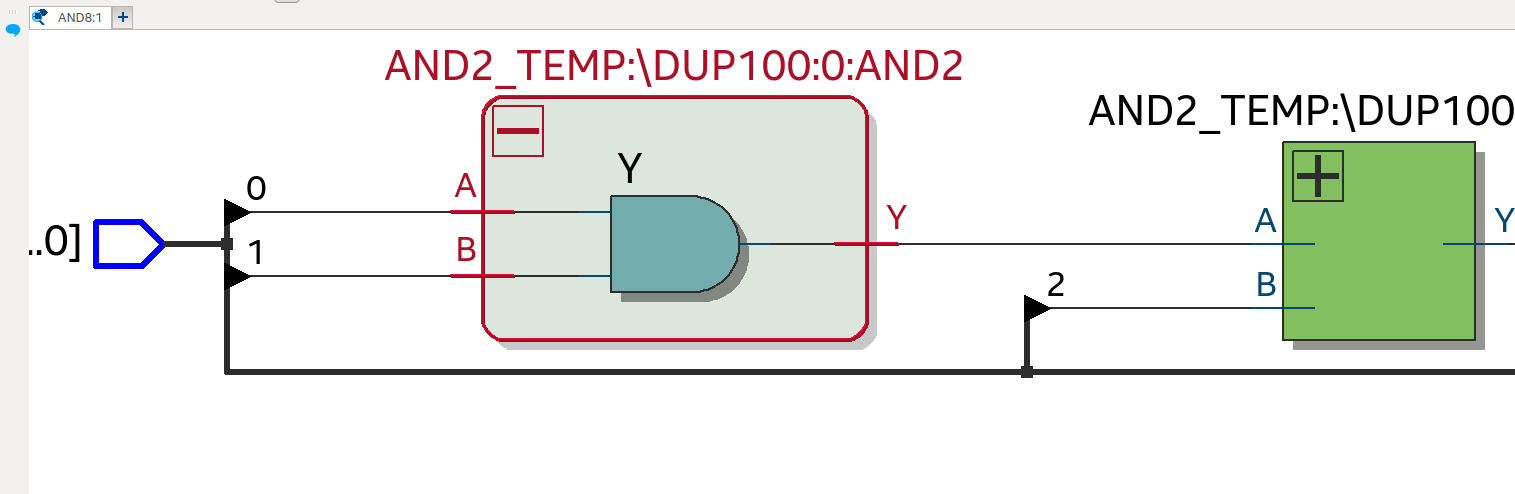
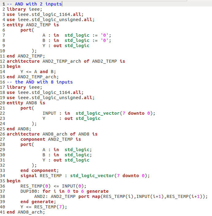
Example of 8 inputs AND gate leys say we need to create 8 input AND gate, and we have already 2 Input AND gate that other developer created it for us and we would like to use it and complicate it more.
Notes
1. This example is not very intuitive as there is much more ealagant way to achive this (using loops in process), in addition we have a signal with size of inputs which is not very intuitive as well
signal RES_TEMP : std_logic_vector(7 downto 0);.
2. there is a way to make Elements more generaic (by using generic keyword) that can make it able to decide size of elemetns, that way we can VHDL more flexible
(click here for generics introduction).
3. generate statments used to duplicate logic in Architecture and they work in parallel which can cause some difficult thinking while designed logic, for simple H\W that do defined work it preffered to use process or function, but in somecase we need to have duplicated logic in architecture.
4. Label is mandatory in the generate statments.
Important case when we want to use geneare is when duplicating sucb devices aka component in the architecture, also when using concurent procedure in the architecture (click here for procedure introduction).
in the below example
we have a AND2 gate which defined earlier, it could be location in other VHDL file as well (we place it here for convinence), we utilized it in the architecture by duplicating it 7 times (for i in 0 to 6) we used to 6 and not to 7 as we used in the generate a index (i + 1), and for that we cannot "scan" it to 7.
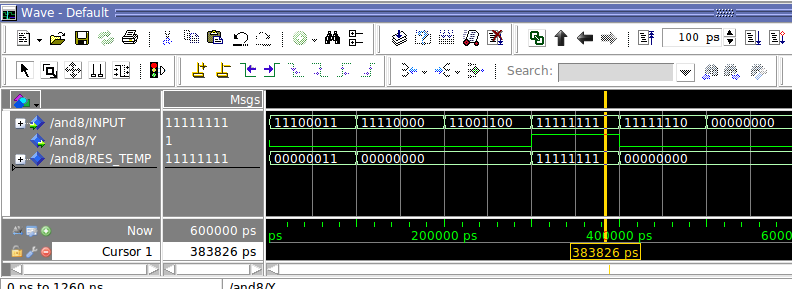
we simulate the Example by using TCL script that test several main cases.
Alternative Example of the AND with 8 inputs using loops here.