writted in VHDL compiled with Modelsim example of counter with async reset
- Every VHDL system must have one
entity and one architecture.- The entity define how the system will be looks from top, aka like box with inputs\outputs
- The architecture define the logic inside the entity
- the architecture mapped to entity using
of operatorBelow are Simple Sync Design System - 4bit counter
● at line 15 all the A-Sync and CLOCK are must appear (mandatory for sync design).
● for Sync system only clock and A-Sync signals should appear in process sensitivity list (mandatory for sync design).
● Note that at line 19 the rising_edge(clk) is the main sync expression.
● std_logic_1164 is very usefull for arithmetic operations therefore it is very easy to implement counter.

1. open modelsim and ensure you are in the directory where counter1.vhd is
2. write vlib work (if already did you can skip, if u not skip command will not do anything)
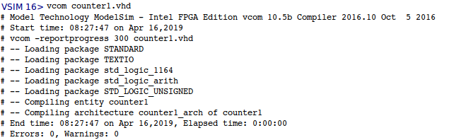
3. to compile write vcom counter1.vhd
then you will see that modelsim will load your VHDL file and compile it , modelsim will store in work folder
data that is relevant to the compilation
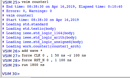
1. write vsim %nameOfEntity% (no .vhd extention)
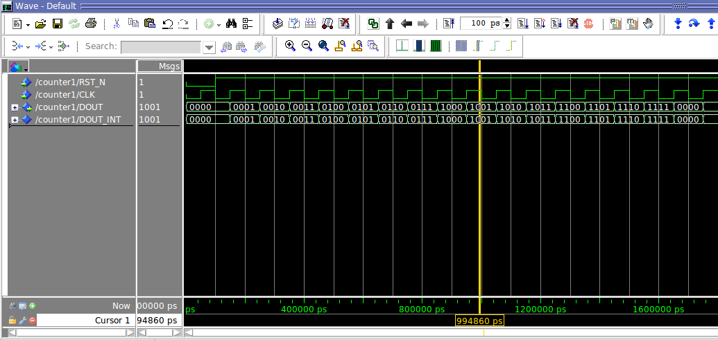
2. to see the waveforms write add wave * the * mean that it will add all the ports\inputs.
3. force CLK 0 , 1 50 ns -r 100 ns it will make the clock signal (repeated)
4. force RST_N 0 , 1 100 ns will put RST_N to 0 for 100 ns then to '1'.
5. run 1800 ns will run for 1800 ns to see that when counter reach end it reset itself to "0000".
we can see when counter reach "1111" in the next clock it reset.