Written in VHDL compiled with Modelsim example of simple AND & OR gate with 2 inputs
Basic Comments
1. Every VHDL system must have one
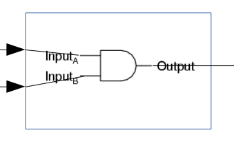
entity and one architecture.2. entity is considered a basic compilation unit - to compile VHDL file it must have at least one compilation unit. - The entity define how the system will be looks from top, aka like box with inputs\outputs.

3. The architecture define the logic inside the entity.
4. the architecture mapped to entity using
of operator
5. entity contain the ports connection, port have direction index, port can be in, out (others will be discussed later). we have two in ports a and b inputs for the gate and two output (out), port must start with '(' and end with ')'
6. every VHDL logic command must be ended with ;
7. in Architecture statments are execuated in concurent way.(not procedural like in C) it mean that order of the statments is not have meaning both happen in "same time".
Assignment to output done with <= operator, you cannot assign to port that is set as in in the entity. also it not legal to read output like this Y_OR_OUT <= Y_AND_OUT;
(legal in VHDL-2008, will be discussed later)
8. architecture have 2 areas, declarative and beheviral the declarative area is above the begin and beheviral after.
we will discuss declarative area of architecture later.
9. not always mandatory but we will use name of architecture and entity in the end of block always. (like end AND_OR_2_1_arch;)
note: in industrial code based on local standards usully it is mandatory to label everything as code gets very complex.
10. we used 2 logic operations and, or in the architectire, will discuss more logic operations later.

This logic system is just a simple AND & OR gates with 2 inputs.
Logic OR will be done with A_INPUT & B_INPUT the result will be stored in Y_OR_OUT,
for Logical AND it similar.
since both statments for output assignment ( <=) are writted in the architecture directly, both will "happen" in the same time and order not important!.
1. open modelsim and ensure you are in the directory where your VHD\VHDL file is
2. write vlib work (if you already did you can skip, if you not skip the command will not do anything)
3. to compile write vcom AND_OR_2_1.vhd
then you will see that modelsim will load your VHDL file and compile it , modelsim will store in work folder
data that is relevant to the compilation - user dont need to deal with content inside the folder.
NOTE - it Strongly recommended for beginner to use same name for file and the entity like here we used AND_OR_2_1. for projects and industrial code this advice may be changed(complex code requires much more files).

we can see that STANDARD PKG (will be discussed later) Loaded, entity and architecture were loaded and compilled by modelsim.
1. write vsim %nameOfEntity% (no .vhd extention)
2. to see the waveforms write add wave * the * mean that it will add all the ports\inputs.
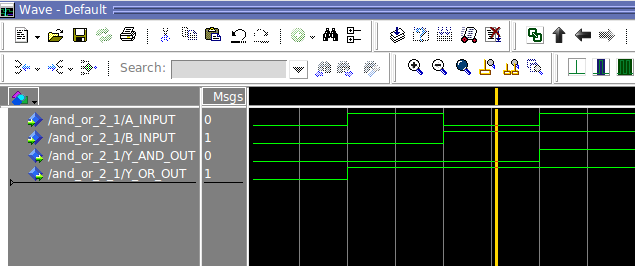
3. force A_INPUT 0 it will force logic 0 to input A_INPUT
4. force B_INPUT 0 it will force logic 0 to input B_INPUT
5. run 100 ns will run for 100 ns , we will see the waveform
we can add more permutation of A_INPUT and B_INPUT to cover all cases and run eatch of them.
NOTE1 - we dont have to eatch time force same command from same state like if A_INPUT is already 0 no need to force A_INPUT 0 again
NOTE2 - usually we will not use force commands but use Test Bench (will be discussed later)
NOTE3 - it preffered to put vcom,vsim and other modelsim commands in a script and run it from modelsim
to run a script write do AND_OR_2_1.tcl (*.do is ok also)


we can see that out entity was loaded from work folder we created earlier.
we can ssee that the system act like expected behaive of and and or gate with 2 inputs.