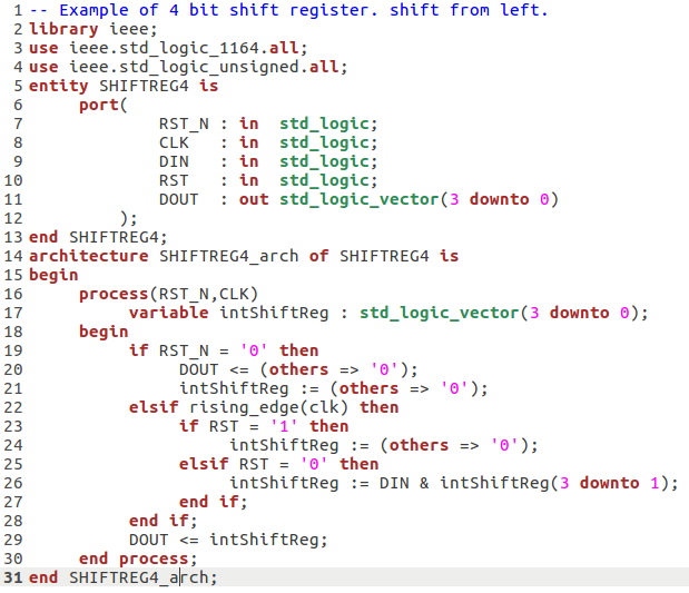
Lets Demonstrate a shift register with sync reset - we will show 4 bit shift register.
system also have a sync reset that will reset the internal status with all the bits accesible.
Notes
1. the "shift" achived by concatenating std_logic_vector is a speciel way, the DIN bit is concatenated from left as MSB with the rest of hte internal valus except the LSB using & operator.
2. we used variable to concatenate it, as variables very usefull in internal calculations, also not that in VHDL (before 2008) we are not allowed to assign to outputs values so instead of
DOUT <= DIN & DOUT(3 downto 1) we used
intShiftReg := DIN & intShiftReg(3 downto 1)
3. we demonstrate better way to "reset" value in vector.
instead of,
DOUT <= "0000";
it much better to use
DOUT <= (others = > '0');
as it not relay on size of the vector and can make your Logic design more flexible.
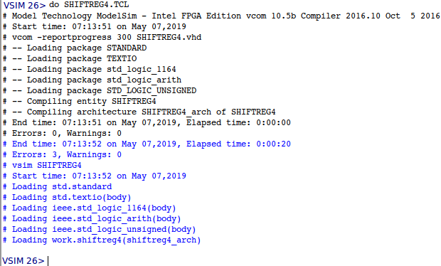
vcom SHIFTREG4.vhd
vsim SHIFTREG4
add wave -divide "clock and reset inputs"
add wave CLK
add wave RST_N
add wave -divide "sync inputs/out"
add wave DIN
add wave RST
add wave DOUT
force CLK 0 , 1 50 ns -r 100 ns
force RST_N 0 , 1 100 ns
force DIN 1
force RST 0
run 300 ns
force DIN 1
run 100 ns
force DIN 0
run 100 ns
force DIN 0
run 100 ns
force DIN 1
run 100 ns
force DIN 1
run 100 ns
force RST 1
run 100 ns
force RST 0
run 100 ns
force DIN 1
run 100 ns
force DIN 0
run 100 ns
force DIN 1
run 100 ns
note that when sync reset is '1' then counter is reset "0000". we can see that waveform look like SHIFT REG, also not that when sync reset is 1 the all values will reset.
