JTAG is stand for Joint Test Action Group which is an IEEE standard (IEEE-1149.X) which originaly used for testing Electrical circuits after it been solder, the JTAG also called TAP which is Test Access Point, in general JTAG is a serial communication protocal that have 4 or 5 pins can be used for multiple purpose, today JTAG is the one the the most commom protocal in the Industry
JTAG is used for
● Debug\Testing ability of the device.
● Storing firmware or programming FGPA\CPLD.
● Boundary Scan Testing
inputs Overview
| TCLK | JTAG have a clock as its synchonius protocol. |
| TRST | TAP Retest, used for resetting JTAG , its an optional input. |
| TMS | TAP Mode Select, used to select working mode, used to control JTAG SM. |
| TDI | TAP data input. |
| TDO | TAP data output. |
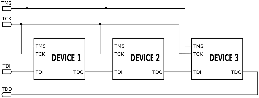
JTAG also can be connected as Daisy Chained with connecting multiple devices
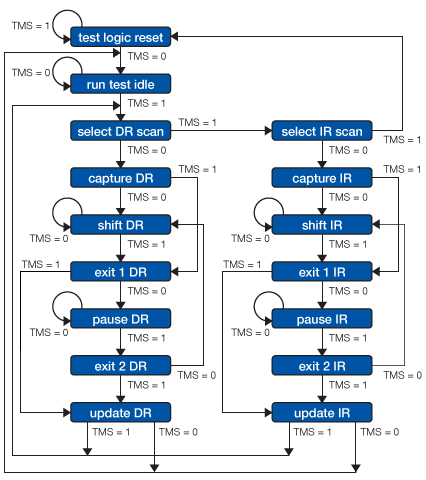
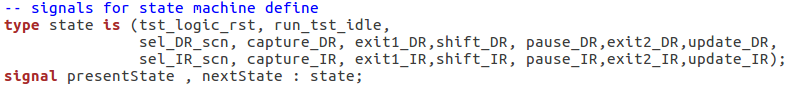
1. JTAG SM have 16 state's in the SM. states defined as type state with thier names.
as thier will used for state machine a signal from type state will be used to define the presentState and the nextState of the state machine.
2. 6 States are stable (constant valus of TMS will keep them in same state)
tst_logic_rst, run_tst_idle, shift_DR, pause_DR,shift_IR, pause_IR
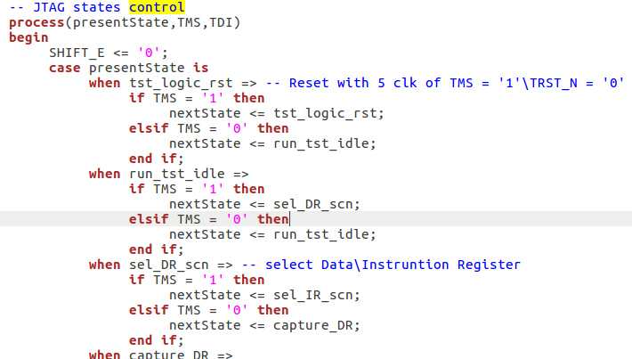
the states contol logic is defined in a a combinational process with case statment that will measure the presentState and assign value to next state based on the TMS input.
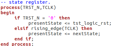
2.1 - tst_logic_rst - will remain if TMS='1',also it can be reset Async way with TRST_N, because it defined in the state register.
2.2 - run_tst_idle - will remain on same state if TMS='1' , if TMS='0' it will go to sel_DR_scn.
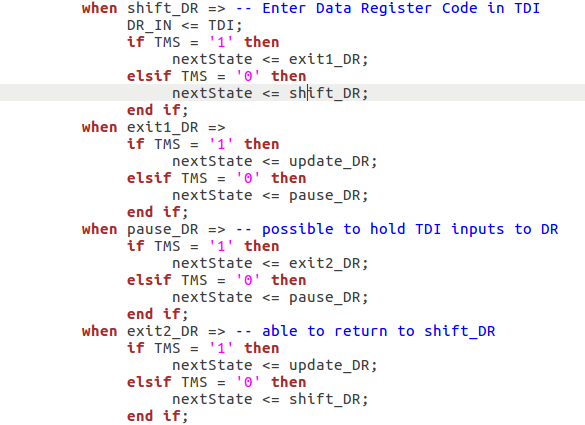
2.3 - shift_DR - will remain on same state if TMS='0', this allowd to enter values to Data Reg while on that state. if TMS='1' we will move to exit1_DR state from where can can decide if to pause it to go to update DR
2.4 - pause_DR - will remain on same state if TMS='0', this allow to pause collection of new inputs from TDI, when TMS='1' we will go to exit2_DR - note that from exit_2 we can decide to return to shift_DR and continue collect inputs.
2.5 - shift_IR - will remain on same state if TMS='0', this allow to collect inputs from TDI to Instruction Register of the JTAG if TMS='1' we will go to exist_IR from where we can go to update_IR.
2.6 - pause_IR - will remain on same state if TMS='0', his allow to pause collection of new inputs from TDI, when TMS='1' we will go to exit2_IR - note that from exit2_IR we can decide to return to shift_IR and continue collect inputs.
3. TMS = 1 will usully keep go to next states, till it reach reset (5 clocks TMS = 1 will reset the SM) so the system support sync reset by using TMS input.
stable states tst_logic_rst,run_tst_idle
state states shift_DR, pause_DR and their near states
● BYPASS Mode.
in most casese to test JTAG we use bypass mode to test if JTAG FSM is working, for that we set IR code to be constant Zeros assume "0000000000"