8259 is an Programmable Interrupt Controller (PIC) that originally designed to work with 8085/8086/8088 Microprosessors. the Chip combine support of multiple interrupts sources (initial 8259 had 8) into single CPU.
the 8259 connected with 8086 CPU using INTR and INTA_N pins. it also possible to connect multiple 8259s to Increase the amount of Interrupts
WHen interrupt occur and CPU acknowalaged it the 8259 will send an Interrupt Vector (vector offset) to the CPU what will decode it and go to the area in the memory where Interrupt code are defined. the 8259 will send the vector via D0-7 Lanes.
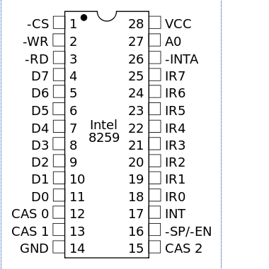
● Data BUS Lane (D 0-7) connected to the Data BUS of 8086 System
● Read\Write Logic Pins -
WR_N and RD_N connect to CPU WR_N and ED_N
CS used to disable enable the Controller
A0 connected to Address BUS.
● Cascade Buffer Pins - CAS0,CAS1,CAS2 and SP_N/EN_N - used to control multiple 8259 devices.
● Interrupt handshake Pins INT and INTA_N used to conenct to 8086 CPU.
● Interrupt requests Lanes - Async Pins that used to request for an Intrerrupt, there is 8 of thouse pins and they have priory IR0 is the highest while the IR7 is the lowst

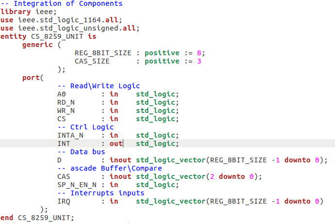
Example of 8259 VHDL Entity (with connect of pins)